

 PL
 EN
 DE
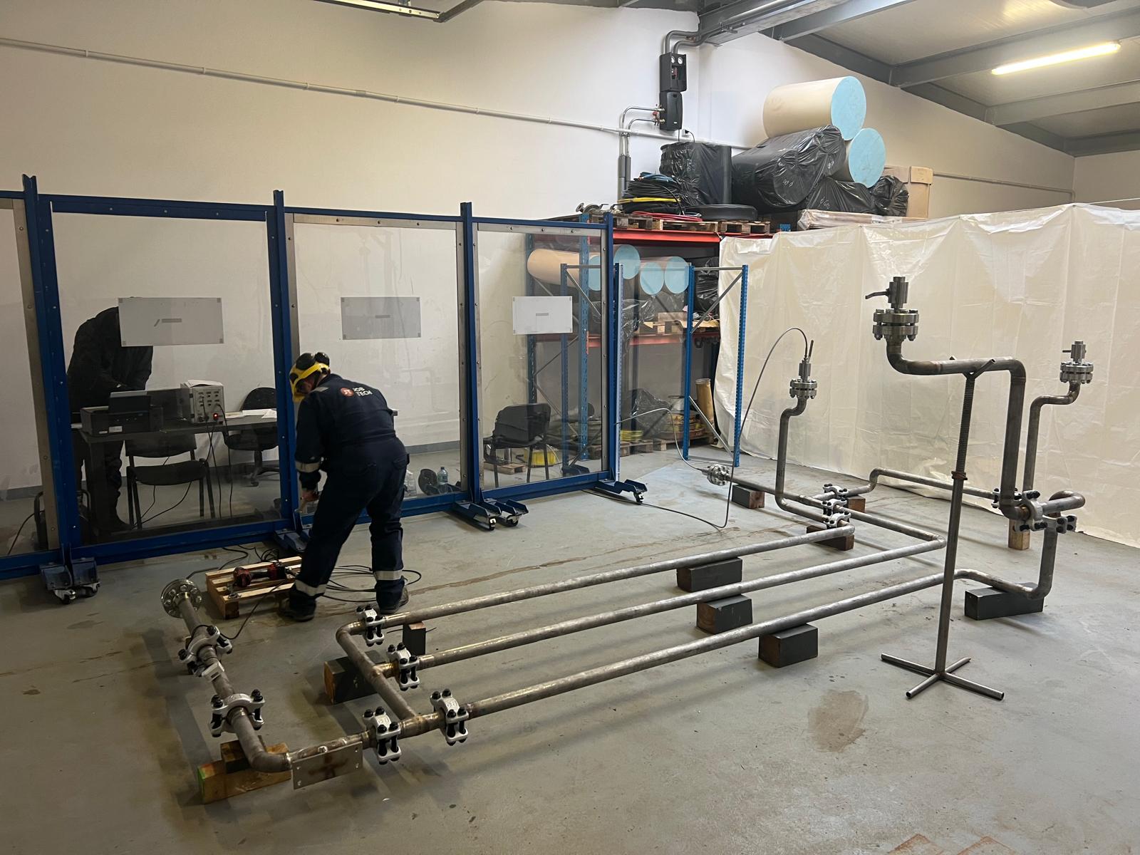
Piping Pressure Testing Before Start-up: Hydrostatic or Pneumatic?
Piping pressure testing before commissioning: preparing test packs and boundaries, when a hydrostatic test is the right choice, why a pneumatic test needs extra safeguards, and what the test records must prove.

Piping pressure testing is the moment when an installed system stops being a collection of welded and bolted components and becomes a proven pressure boundary. Until the test is passed and signed off, a line cannot be flushed, filled with process media or handed over to operations, so a delay here pushes back every later commissioning milestone.
The choice of method reaches well beyond the test itself. A hydrostatic test puts tonnes of water into the system. A pneumatic test keeps the line dry but stores enough energy in compressed gas to turn a weld defect into a serious incident. For JobTech, pressure testing is a routine part of the mechanical and commissioning scope we deliver for equipment manufacturers and EPC contractors in Poland and abroad.
Why piping pressure testing is still required after NDT
Radiography, ultrasonic testing and visual inspection check welds against acceptance criteria, often on a sample of joints only. They say nothing about flanged connections, valve bodies or gaskets, and they never load the system as a whole. The pressure test does: every component inside the boundary is stressed above its design condition at the same time.
ASME B31.3 therefore requires heat treatment to be completed before the leak test and joints to remain uninsulated so they can be examined under pressure. Painting and insulation have to wait for the result.
Preparing the test pack and the test boundaries
Tests are organised around test packs. Each pack groups lines with compatible design conditions and contains marked-up P&IDs and isometrics, test pressures, the weld map with NDT status, the list of temporary blinds, vents and drains, and gauge calibration certificates. Setting the boundary is largely about what stays out of the test. Pumps, compressors, control and relief valves, rupture discs and many in-line instruments are removed and replaced with temporary spools or isolated behind rated blinds. Spring hangers are locked, because supports on a gas line were never designed for the weight of a pipe full of water.
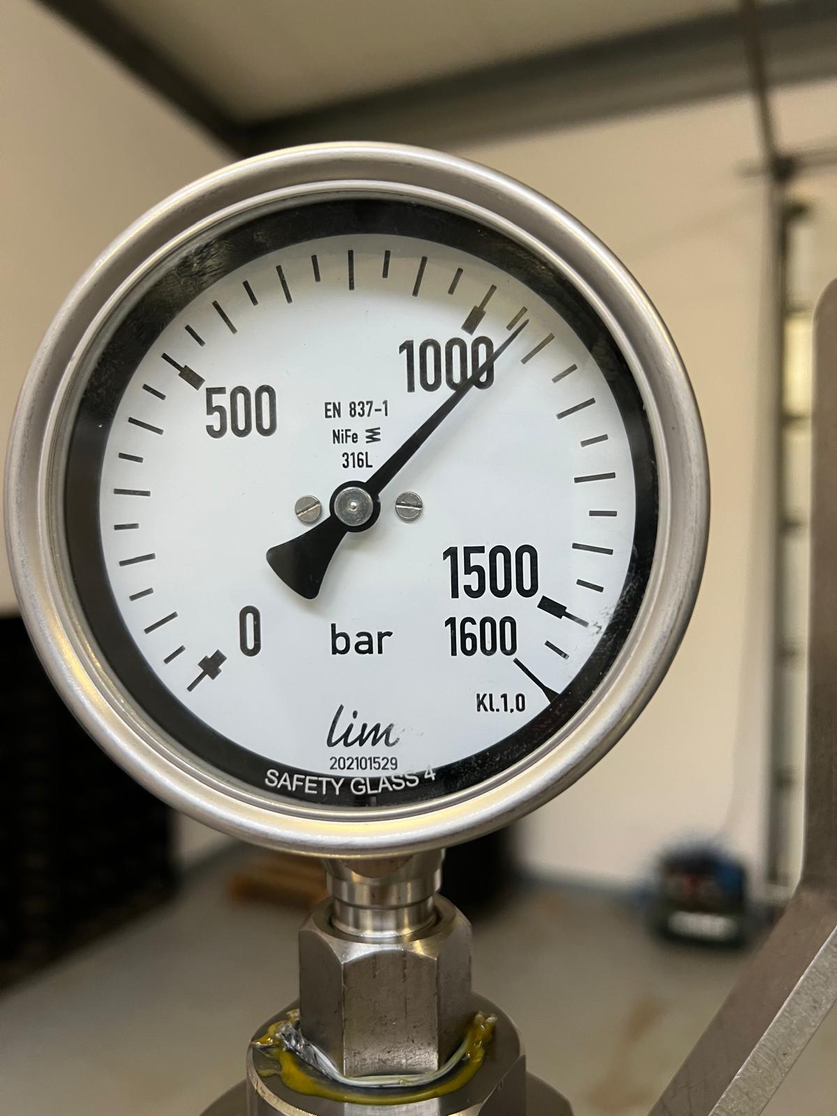
Gauges are selected so that the test pressure falls in the middle part of the scale, usually with a pressure and temperature recorder alongside. In tall systems every ten metres of water column adds roughly one bar at the lowest point, so the procedure states where the test pressure is measured.
Hydrostatic testing in practice
Hydrostatic testing is the default method in European and American practice alike. Under the Pressure Equipment Directive and EN 13480-5, the test pressure is the greater of 1.25 times the maximum loading at maximum allowable temperature and 1.43 times the maximum allowable pressure PS. ASME B31.3 requires at least 1.5 times the design pressure, corrected for allowable stress at test and design temperature. The procedure also defines water quality. For austenitic stainless steel the chloride content is typically limited to a few tens of mg/l, because chlorides left in crevices can initiate pitting and stress corrosion cracking. Filling starts from the low point with every high-point vent open until the water runs free of air, since trapped air brings stored energy back into the test.
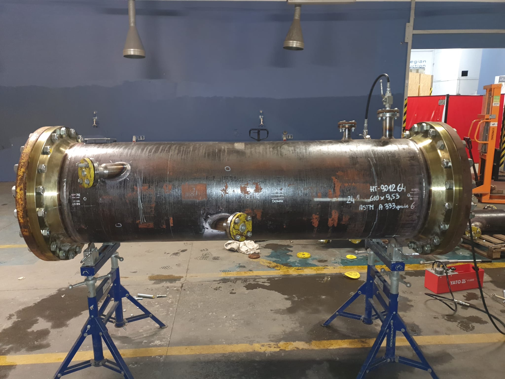
Pressure is raised gradually, held for the specified period (at least ten minutes under ASME B31.3) and usually reduced to design pressure while the inspector examines every joint. Temperature is the main source of misleading readings: in a liquid-full, blocked-in section a few degrees can shift the pressure by several bar, enough for sunshine on an outdoor rack to mask a small leak.
Pneumatic testing and stored energy
Pneumatic testing is chosen where water cannot be tolerated: instrument air and gas systems, lines that must stay dry, cryogenic service or large-bore lines whose supports cannot carry the water. ASME B31.3 sets the test pressure at 1.1 times the design pressure and treats the method as an exception the owner has to accept.
The reason is energy. Water is almost incompressible, so a failure during a hydrostatic test usually ends with a spray and a drop on the gauge. Gas at the same pressure and volume stores hundreds to thousands of times more energy, released as a blast and flying fragments. Material toughness at test temperature must rule out brittle fracture, and ASME PCC-2 gives a method for calculating the safe distance that defines the exclusion zone.
After a preliminary check at low pressure, pressure is increased in steps with holds, then reduced to design pressure before anyone approaches the joints with a bubble solution. While pressure rises, the team watches gauges and recorder from behind barriers.
| Criterion | Hydrostatic test | Pneumatic test |
|---|---|---|
| Test medium | Water of specified quality | Air or nitrogen |
| Test pressure (ASME B31.3) | At least 1.5 × design, temperature-corrected | 1.1 × design pressure |
| Stored energy | Low | Very high, sets the exclusion zone |
| Main hazards | Support overload, freezing, residual water | Brittle fracture, blast, fragments |
| Leak detection | Joint inspection, pressure hold | Bubble solution at reduced pressure |
| After the test | Draining, drying, preservation if required | Depressurisation only |
Reinstatement and test records on export projects
A passed test is complete only when the system has been reinstated. Temporary blinds are removed against the blind register, instruments and valves go back in, permanent gaskets are fitted and hanger locks released. Joints broken after the test are checked again in a service leak test. A test blind discovered during start-up costs far more than the hour spent closing out the register.
On international projects the records are reviewed as closely as the test. The client expects a certificate signed by the contractor, the client’s representative and often a third-party inspector, backed by calibration certificates, the pressure and temperature chart and a closed punch list. JobTech carries out tests to EN 13480, ASME B31.3 and project specifications such as NORSOK L-004 where required, within the client’s test pack and witness point system.
Do you need pressure testing before start-up?
If your installation is approaching mechanical completion, agree the test strategy early, together with the drying and reinstatement that follow it. Our team can review your test packs, prepare the procedures and carry out hydrostatic and pneumatic tests on site, in Poland or abroad.

Have questions about industrial installations?
Contact our team — we will be happy to discuss your project requirements and propose the optimal solution.
Get in toucharrow_forward